1. Make sure automobile stop in a secure position. Apply the emergency brake. Raise the automobile on jack stands.
2. Mark the location of the push rod where it exits the brake chamber of the brakes with chalk.
3. Remove the push rod from the brake chamber. Remove it out of place with a screwdriver.
4. Measure the distance between the brake chamber and the chalk line with a tape measure. This will set the stroke range, which should be below 3/4 inch. If it exceeds 3/4 inch, it means that the brake requires an adjustment.
5. Turn the slack adjuster bolt with an adjustable wrench until you feel some resistance. This bolt is located at the connection point between the brake chamber and the s-camshaft. Determine if you are turning the bolt in the correct direction by monitoring the push rod to see if it is pulling outward from the brake chamber. If so, you are turning the bolt in the correct direction.
6. Adjust a slight distance between the brake drum and linings. Turn the bolt in the opposite direction from which you just turned it. Make a 1/4 to 1/2 turn in this direction with an adjustable wrench.
7. Replace the push rod by pressing it back into place.
8. Apply the brake pedal. This should be the pressure typically used to stop the automobile.
9. Measure the distance between the brake line and the drum with a tape measure. It should be below 1/10 inch between both objects. Release the brake. Mark the location of the push rod with chalk. Apply the brake again, measure the distance between the chalk mark and the current location of the push rod. It should be below 2 inches between the mark and the push rod while brake applied. Your slack adjusters will be properly set.
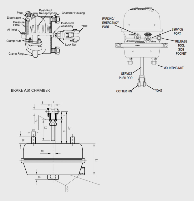
The front brake air chambers are solid steel housings connected to an air compressor. Each air brake chamber contains a pressure bleed valve and a push rod. The push rods have a spring return on the interior and a pressure plate the spans the width and depth of the chamber. When the brake pedal is depressed, air from the compressor is pumped into the chamber. This drives the push rod out with upwards of 1,000 pounds of force. Yoked to the end of the push rod is an S-cam.
The S-cam is a long rod that sits in the interior of the drum brakes. When it turns, it forces out the surrounding brake shoes against the interior of the wheel drums, arresting the tires. Air pressure is used because traditional hydraulic chambers would not be able to create sufficient fluid pressure to stop the tires as quickly.
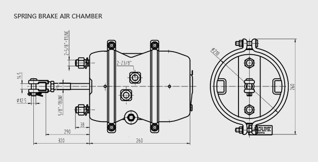
Rear spring brake air chambers perform the same function as front brake air chambers, but they also double as a parking brake, thus their design is a little more complex. These are a dual-chamber system. The push rod and air chamber as present as usual, but behind this chamber is a second one which contains a powerfully coiled braking spring on a solid plate, much like the plate the push rod ends in. It’s kept in check by a latch which connects directly to the parking break lever in the driver’s cab.
The brake functions normally when the pedal is depressed, but if the parking brake lever is deployed, the latch snaps away from the spring and it manually drives the push rod forward with several hundred pounds worth of force. In order to disengage the parking brake, the brake pedal must be depressed, filling the first chamber with air and forcing the spring back until the latch catches hold of it again